Вычисление Круга, чтобы Рисовать
Следующий пример рисует круг модуля, центрированный в начале координат. Точный рисовавший круг зависит от взгляда области просмотра круга. Цель состоит в том, чтобы рисовать круг с полилинией, которая имеет минимальное число заметных долей. С командой VPORTS, Вы можете создавать четыре области просмотра и затем нажимать на один и раскрывать на круге, затем нажимать на другой и копировать от этого. Когда Вы REGENALL, каждая область просмотра вычисляет ее собственный минимально сегментированное представление полилинии круга.
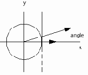
Это - то, как пример вычисляет необходимое число долей линии в полилинии. Сначала, учитывая круг данного радиуса, который центрирован в начале координат и расположен в XY плане, и дан вертикальную линию, которая пересекает X ось в радиусе - 0.5 пикселов, определять угол между X осью и долей линии, которая простирается от начала координат к сути, где вертикальная линия пересекает круг. Два pi разделенный этим углом обеспечивает минимальное число долей, необходимых полилинией, чтобы напомнить круг. Пользователь не будет способен дифференцировать индивидуальные доли линии, которые составляют круг, потому что визуальные различия - меньше чем пиксел.

Adesk::Boolean
AsdkTesselateSamp::worldDraw(AcGiWorldDraw *pW)
{
// Draw a red 1x1 drawing-unit square centered at the
// world coordinate origin and parallel to the XY-plane.
//
const Adesk::UInt32 num_pts = 5;
AcGePoint3d verts[num_pts];
verts[0] = verts[4] = AcGePoint3d(-0.5, -0.5, 0.0);
verts[1] = AcGePoint3d( 0.5, -0.5, 0.0);
verts[2] = AcGePoint3d( 0.5, 0.5, 0.0);
verts[3] = AcGePoint3d(-0.5, 0.5, 0.0);
pW->subEntityTraits().setColor(kRed);
pW->geometry().polyline(num_pts, verts);
// If regenType is kAcGiSaveWorldDrawForProxy, return
// Adesk::kTrue, otherwise return Adesk::kFalse to trigger
// calls to viewportDraw().
//
return (pW->regenType() == kAcGiSaveWorldDrawForProxy);
}
void
AsdkTesselateSamp::viewportDraw(AcGiViewportDraw *pV)
{
static double two_pi = atan(1.0) * 8.0;
// Get the number of pixels on the X- and Y-edges of
// a unit square centered at (0.0, 0.0, 0.0), in
// world coordinates.
//
AcGePoint3d center(0.0, 0.0, 0.0);
AcGePoint2d area;
pV->viewport().getNumPixelsInUnitSquare(center, area);
// If the area values are negative, then we are in
// perspective mode and the center is too close or
// in back of the viewport.
//
if (area.x > 0.0) {
// Print out the number of pixels along the
// Y-axis of the unit square used in
// getNumPixelsInUnitSquare.
//
AcGeVector3d norm(0.0, 0.0, 1.0);
AcGeVector3d dir(1.0, 0.0, 0.0);
char buf[100];
sprintf(buf, "%7.3lf", area.y);
pV->geometry().text(center, norm, dir, 1.0, 1.0, 0.0, buf);
// Draw a circle that depends on how big the circle
// is in the viewport. This requires
// figuring out the fewest number of segments needed
// by a polyline so that it doesn’t look segmented.
//
// The worldDraw() and viewportDraw() of
// an entity in a viewport are only called during a
// regen and not necessarily during a ZOOM or PAN.
// The reason is that a regen produces something
// akin to a very high resolution image internally,
// which AutoCAD can zoom in or pan around. That is,
// until you get too close to this image or any of
// its edges, at which point a regen is internally
// invoked for that viewport and a new internal
// image is created (ready to be mildly zoomed and
// panned).
//
double radius = 0.5;
double half_pixel_hgt = 2.0 / area.x; // In WCS
int num_segs = 8;
double angle = two_pi / num_segs;
if (half_pixel_hgt > radius / 2) {
// The circle is approximately the same or less
// than the size of a pixel. So, generate a very
// small octagon.
//
num_segs = 8;
} else {
// Given a circle centered at the origin of a
// given radius in the XY-plane, and given a
// vertical line that intersects the X-axis at
// ’radius - half a pixel’, what is the angle
// from the X-axis of a line segment from the
// origin to the point where the vertical line
// and the circle intersect? Two pi divided by
// this angle gives you a minimum number of
// segments needed by a polyline to look like
// a circle and not be able to differentiate
// the individual segments because the visual
// differences are less than the size of a
// pixel. (This is not the only way to figure
// this out but it’s sufficient.)
//
angle = acos((radius - 1.0 / (area.x / 2.0)) / radius);
double d_num_segs = two_pi / angle;
// Limit the number of segments from 8 to
// 128 and use whole numbers for
// this count.
//
if (d_num_segs < 8.0) {
num_segs = 8;
} else if (d_num_segs > 128.0) {
num_segs = 128;
} else {
num_segs = (int)d_num_segs;
}
}
// Calculate the vertices of the polyline from the
// start, around the circle, and back to the start
// to close the polyline.
//
angle = 0.0;
double angle_inc = two_pi / (double)num_segs;
AcGePoint3d* verts = new AcGePoint3d[num_segs + 1];
for (int i = 0; i <= num_segs; i++, angle += angle_inc)
{
verts[i].x = center.x + radius * cos(angle);
verts[i].y = center.y + radius * sin(angle);
verts[i].z = center.z;
}
pV->geometry().polyline(num_segs + 1, verts);
delete [] verts;
}
}
Использование Границ Обрезки в AcGi
ObjectARX позволяет Вам определять границу отсечения для геометрии, содержащейся в пределах таблиц перекрестных ссылок и блоков. Часть границы обрезки AcGi API позволяет составные объекты (блоки и объекты, которые ведут себя подобно блокам) чтобы выразить эти границы обрезки AcGi выполнению.
В течение worldDraw () или viewportDraw () любой drawable может определить многоугольную границу обрезки, чтобы отсечь ее графику. Следующие разделы описывают, как использовать эту особенность API.
